This section covers the basic hardware components of a computer and how they operate in a computer system. It covers:
– Main operations of CPU
– MARIE
– Bus
– ISA
– Instruction Processing FDE cycle
– Microoperations
– Skipcond
– Assemblers
– CISC and RISC
Main operations of CPU:
(1) Process instructions on data.
(2) Reads from input and writes to the output.
(3) Reads from and stores to Memory.
(4) Keeps track pf what to do/ where to go next.
Datapath = consists of ALU and registers that are interconnected by data bus that is also connected to main memory.
ALU = carries out logical and arithmetic operations as directed by control unit.
Registers = hold data that can be readily assessed by the CPU; implemented by D flip-flops.
Clock cycle time = 1/clock frequency

The second equation is the same as 1st equation but it illustrates how the CPU time equals seconds / program; it is because instructions and cycles are present at the numerator and denominator and they cancel each other out.
MARIE = Machine Architecture that is Really Intuitive and Easy:
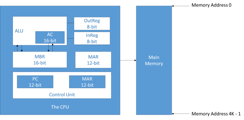
(1) 2’s C binary data representation.
(2) Stored program, fixed word length.
(3) 4k words of word addressable main memory.
(4) 16-bit data words.
(5) 16-bit instructions.
InReg = Holds data received from the Input Device.
OutReg = Holds the data to be sent to the Output Device.
AC = General purpose register holds data the CPU works with.
MAR = Holds the address of the data being referenced from/to memory.
MBR = Data read from or to be written to Memory.
PC = Address of the next instruction to be executed.
IR = The next instruction to be executed.
Marie uses a direct addressing and an indirect addressing mode:
– Direct addressing mode: address of the operand is explicitly stated in the instruction.
– Indirect addressing: address of the operand is given in the instruction.
Bus:
– This is a set of wires used as a shared but common datapath to connect multiple subsystems within the computer.
– At any time, only one component can use the bus.
– Bus movies data from place to place.

ISA (Instruction Set Architecture):
– specifies the instructions that the computer can perform.
– MARIE ISA = 13 instructions only
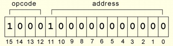
– ISA describes the format of the instructions:

(1) Opcode = the operation/ type of instruction
(2) Address = of the the operand.
Instruction Processing – FDE(Fetch-Decode-Execute) cycle:
(1) Fetch instruction from Memory and place it in IR.
(2) In IR, decode to determine what needs to be done next.
(3) If a memory value(operand) is involved in the operation, it is retrieved and placed in MBR.
(4) The instruction is executed.
Microoperations:
Each of the instructions consists of sequence of smaller instructions.
For example:

M[X] = actual data value stored in memory location X. In the example, M[X] = M[MAR]; data is stored in MAR.
← = transfer of bytes to a register or memory location.
Skipcond:
opcode = 10002.
– Bits 11 and 10 specify the condition to be tested.
– The address part of the instruction is used to specify the condition.
The below code shows how the skipcond is written as a microoperation.

Assemblers:
They translate instructions from “human” language into the machine language that is understandable to computers.
They create an object program file from mnemonic score code in 2 passes:
– 1st pass = builds a symbol table.
– 2nd pass = instructions are completed using the values from the symbol table.
CISC (Complex Instruction Set Computers):
– Each single instruction executes multiple number of low-level instructions
– Multiple addressing modes
RISC (Reduced Instruction Set Computers):
– Each instruction is a single low-level instruction.
– Simple addressing modes.
– Faster than CISC.

